Symptoms
This 2004 Corsa 1.2 arrived with dash and engine auxiliaries already stripped and its trims and covers in the boot. In fact the ECM was missing and had to be sourced from the previous repairer; so a good start. The car had an original complaint of a sudden no-start condition after seemingly faultless running, the previous diagnosis had condemned the engine ECU and I was called for an independent opinion.
On arrival I found the engine would crank with good speed but wouldnĪ»t fire. From previous dealings with this model I know the engine MIL and oil MIL are controlled by the ECM, and here I had the engine MIL flagged but no oil MIL: a possible early clue. Checking the system with the scan tool found P1615 WRONG VEHICLE ID FROM BODY CONTROLLER and P1616 WRONG VEHICLE ID FROM INSTRUMENT, with both faults logged as present and unable to clear. At this early stage there was no suggestion that I was dealing with the usual suspects: CKP, CMP, fuel delivery, or any base calculation sensor. This problem was leaning towards a CAN issue or an exchange of data between control units.
Investigating the electrical system
ItĪ»s helpful to gain some knowledge of the electrical architecture of the vehicle under test: where control units are located, their master/slave relationship, and the number of networks will prove a worthwhile research.
Here is the basic layout I found for the main control units.
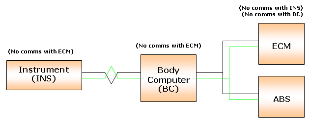
Already a bigger picture is emerging about the problem and the likely area to start looking. The ECM is reporting a problem with both INS and BC, yet data exchange between INS and BC themselves appears OK (no DTCs) making the ECM a common denominator. Both INS and BC appear to be functioning fine with all their associated auxiliaries working, so a power supply issue is unlikely. Also I have good communication between the scan tool and ECM, allowing different self-activations and accurate live parameter readings, so again a power supply issue at the ECM is unlikely. The next step is to verify the data transmission line: the CAN bus.
Checking with the PicoScope
ThereĪ»s no better place to take measurements than directly at the control unit. Why? You are seeing what the control unit sees. Fig.1 shows a typical recording taken from the two CAN cables at the ECM.
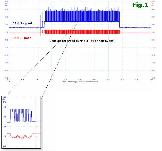
This is far from the pair of mirror-image signals we would normally expect to see. CAN H represents a good signal structure with well-defined dominant and recessive bits, but CAN L displays no recognisable bit transmission and its line stability has drifted low.
TIP: Expect some networks to revert to single-wire CAN if such a problem exists. However, this ECM remained off-line throughout.
 CAN relies on differential transmission, where a recognisable message is achieved by the difference in voltage between the two lines. Ordinarily in this case a recessive bit would result in 0 V ?between two cables and a dominant bit would result in 2 V. With our problem car the erroneous CAN L will affect the overall data packet received. CAN relies on differential transmission, where a recognisable message is achieved by the difference in voltage between the two lines. Ordinarily in this case a recessive bit would result in 0 V ?between two cables and a dominant bit would result in 2 V. With our problem car the erroneous CAN L will affect the overall data packet received.
This is good confirmation that a CAN fault exists, so now we must try to isolate the problem. Each node was checked to monitor general line activity and make some comparisons. I found good CAN signal structure at the ABS and BCM, leaving only the ECM affected by the fault. This has localised the problem to engine bay area and focuses on the wiring between the ECM and its harness splice onto the CAN line.
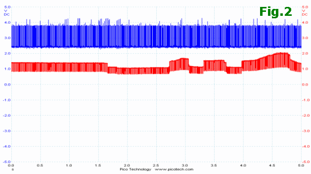
Fig.2 was recorded during a wiggle test on the engine harness and shows a direct effect on signal structure when the harness is flexed. At one point I managed to get the CAN lines close to normal, at which point the ECM eventually allowed a successful start for first time in a long while. Stripping the harness eventually revealed the fault.
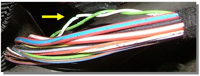
A small section of the CAN cabling had suffered from corrosion badly and had eaten away nearly all of the cable strands. It is likely a result of chafing on the inside of its protective conduit which is supposed to protect the harness from such failure ©C ironically. Because the test points were intentionally placed at the rear of the control unit, positive confirmation of a problem was easy. Generally, taking CAN measurements at mid-harness connections or perhaps at a CARB socket is a valid circuit performance check; but just be aware that a spliced take-off with an open circuit will be near-invisible when you check the main line and its termination resistors.
Lessons learned
Thinking back to the beginning, having the engine MIL flagged but no oil MIL is a peculiar system response to this CAN line fault but one worth remembering. Operational characteristics arenĪ»t something read in a manual, but are learnt through hands-on experience. Hope it helps.
Ųõ╦³▌oī¦┘Y┴Ž >
|